Progress Photos for March 29, 2003
Thrust Test and New Engine Photos
Back to Photo Gallery page.Wright Redux and Packer Engineering crews did some thrust testing today to see just how much push we can get from our drive train and propellers. We rigged up some sand bags and an electronic scale to perform the test which proved that we are very close to our goal.
But the first set of images show machining progress on the replica engine thus far.
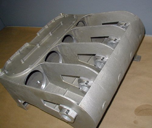
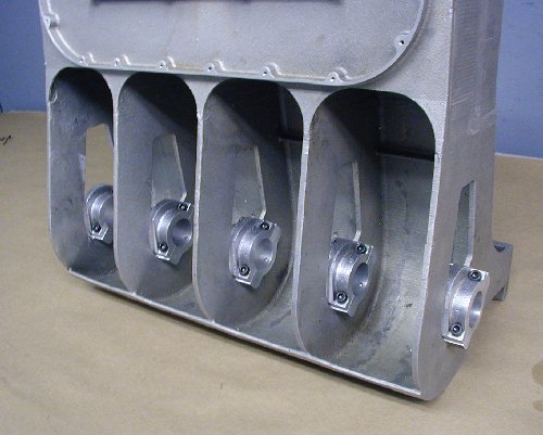
1. Crankshaft bearings are bolted in place.
2. Camshaft bearings are added as well.
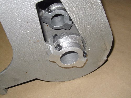
3. Close up of crankshaft bearings.
4. Another view of the crankshaft bearings.
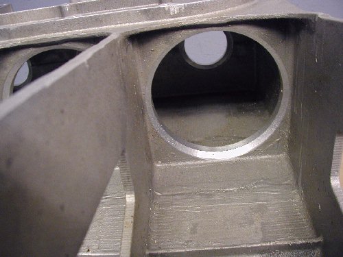
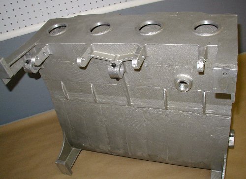
5. Interior surfaces are machined.
6. Holes are threaded.
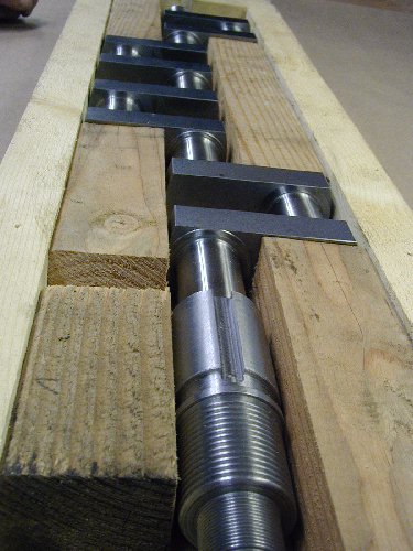
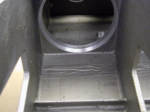
7. New machining to crankshaft is evident.
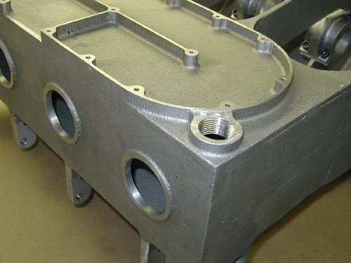
8. The intake manifold is machined and water jacket ports are threaded.
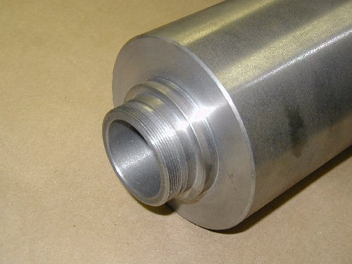
9. Cylinders are machined and threaded.
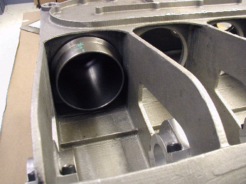
10. A cylinder is shown in place.
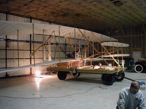
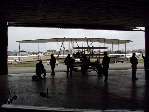
11. Preparations begin for the thrust test.
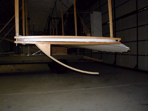
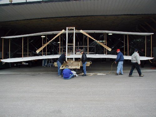
12. To prevent wingtip damage, Mark Miller has designed and installed these edge protectors. They'll keep the ends from touching the ground in case a side wind gust tips the Flyer.
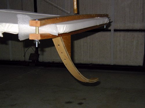
13. Here's another view of the wingtip guard.
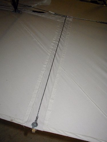
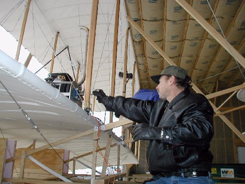
14. We've noticed that control wire movement is causing some wear in the fabric covering. Jean Mumford has designed and temporarily sewn an extra layer of fabric beneath the moving wires. They will be removed before the Flyer is displayed at the Museum of Science and Industry in Chicago.
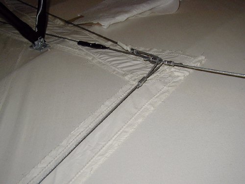
15. A protective layer of fabric lays under the wing warping control wires.
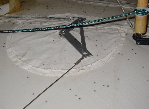
16. A protective layer of fabric lays under the bell crank.
17. The crew works on the rigging for the thrust test which uses sand bags and an electronic scale.
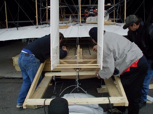
18. The thrust of the props will pull the Flyer forward, lifting the sandbags through a series of wires and pulleys. Having done so, the scale beneath the sandbags will read zero weight as the load is removed.
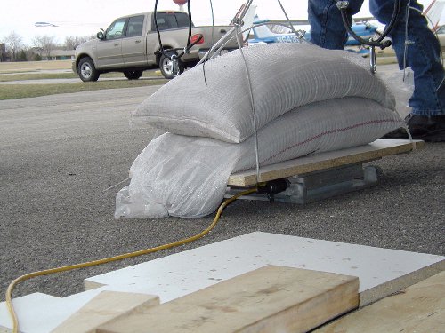
19. Sandbags rest on the electronic scale.
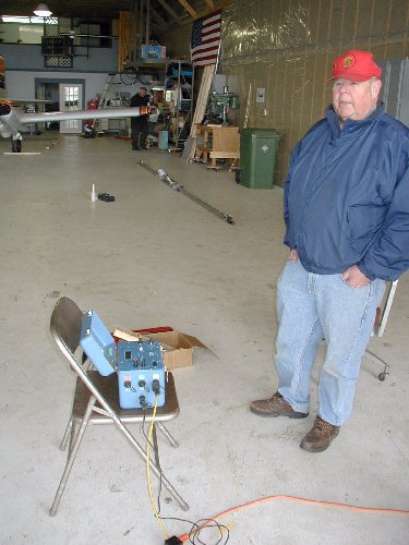
20. Ed Meyer stands ready to note the readout.
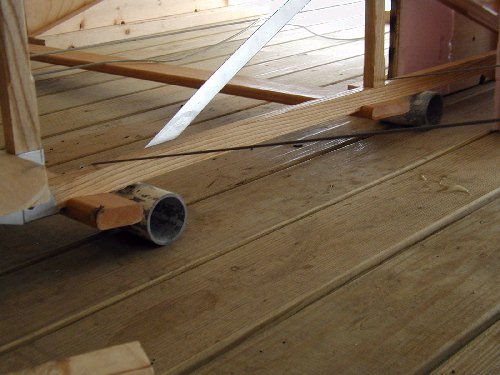
21. How can the Flyer move forward? This simple but effective means of placing pieces of pipe beneath the Flyer's undercarriage allows it to roll freely forward on the trailer.
22. The engine is fired up and the props begin to spin.
23. As the engine is gradually revved to full power, Bill Mumford holds in place, a friction operated revolution counter (tachometer) onto the shaft that powers the props.
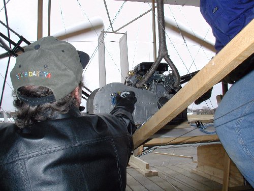
24. Bill reads the RPM as the engine power is increased.
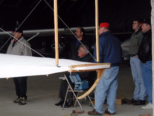
25. The crew listens for Bill's RPM reading to then compare it with the scale reading.
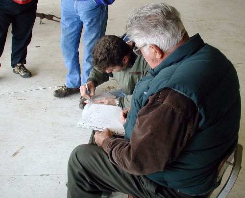
26. Dr. Ken Packer writes down the readings as Steve Meyers plots the two numbers.
27. The crew discusses the results. Conclusion: We're nearly there. A simple gear change will allow us to produce the needed thrust.
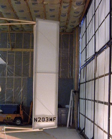
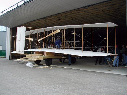
28. The Spirit of Glen Ellyn proudly shows off her tail numbers knowing she's ever closer to the first day of flight.